Aventuras y Desventuras de un hobbyist

Aventuras y Desventuras de un hobbyist....

Cyclone PCB - Y rod idler redesign

Here the part already 3D printed:

Don't forget to look at the base to see the logo

Parsing NMEA sentences in C


I am starting a new project involving a GPS with Bluetooth capabilities, so far I have been able to get the information from the GPS module but it comes as NMEA sentences containing the precious data.

So before doing something fancy on the computer it is needed to decode the information

There are 19 interpreted sentences:
   $GPBOD - Bearing, origin to destination
   $GPBWC - Bearing and distance to waypoint, great circle
   $GPGGA - Global Positioning System Fix Data
   $GPGLL - Geographic position, latitude / longitude
   $GPGSA - GPS DOP and active satellites 
   $GPGSV - GPS Satellites in view
   $GPHDT - Heading, True
   $GPR00 - List of waypoints in currently active route
   $GPRMA - Recommended minimum specific Loran-C data
   $GPRMB - Recommended minimum navigation info
   $GPRMC - Recommended minimum specific GPS/Transit data
   $GPRTE - Routes
   $GPTRF - Transit Fix Data
   $GPSTN - Multiple Data ID
   $GPVBW - Dual Ground / Water Speed
   $GPVTG - Track made good and ground speed
   $GPWPL - Waypoint location
   $GPXTE - Cross-track error, Measured
   $GPZDA - Date & Time

The data I am getting comes only in 5 sentences:
   
   $GPGGA - Global Positioning System Fix Data
   $GPGSA - GPS DOP and active satellites 
   $GPGSV - GPS Satellites in view
   $GPRMC - Recommended minimum specific GPS/Transit data
   $GPVTG - Track made good and ground speed
  
From these 5 I am only interested in $GPRMC The lines of data are
something similar to these two:

eg1. $GPRMC,081836,A,3751.65,S,14507.36,E,000.0,360.0,130998,011.3,E*62
eg2. $GPRMC,225446,A,4916.45,N,12311.12,W,000.5,054.7,191194,020.3,E*68


           225446       Time of fix 22:54:46 UTC
           A            Navigation receiver warning A = OK, V = warning
           4916.45,N    Latitude 49 deg. 16.45 min North
           12311.12,W   Longitude 123 deg. 11.12 min West
           000.5        Speed over ground, Knots
           054.7        Course Made Good, True
           191194       Date of fix  19 November 1994
           020.3,E      Magnetic variation 20.3 deg East
           *68          mandatory checksum
So to decode  we need to understand that where a numeric latitude or longitude is given, the two digits immediately to the left of the decimal point are whole minutes, to the right are decimals of minutes, and the remaining digits to the left of the whole minutes are whole degrees.
      eg. 4533.35 is 45 degrees and 33.35 minutes. ".35" of a minute is exactly 21 seconds.
      eg. 16708.033 is 167 degrees and 8.033 minutes. ".033" of a minute is about 2 seconds

So I wrote a small program that outputs a json file, although I have it divided into 3 files I am posting it as a whole unit:


Once we have this file we can use it in many webapps to display the location and some information about the points, the file will look like:
There are many smart formats and visualizers to display this info such as geoJson, tileJson,
 GPX (a standard format used with many devices and programs, including Garmin's eTrex, GPSMAP, Oregon, Dakota, Colorado, & Nüvi series), Google Earth (.kml/.kmz), Google Maps routes (URLs), Geocaching.com (.loc), FAI/IGC glider logs, Microsoft Excel, Google Spreadsheets,XML feeds, Garmin Forerunner (.xml/.hst/.tcx), Timex Trainer, OziExplorer, Cetus GPS, PathAway, cotoGPS, CompeGPS, TomTom (.pgl), IGN Rando (.rdn), Emtac Trine, Suunto X9/X9i (.sdf), Fugawi, NetStumbler, and of course tab-delimited or comma-separated text.


Finally  you end up with a nice map similar the one below:


Reading 12 ADC channels on the Atmega32u4

The Atmega32u4 has 12 Analog inputs, for single ended input mode and according to its datasheet we can call the different channels changing the values on the ADMUX registers(MUX4:0) although it uses 5 bits to select the channels only 3 are really used (MUX2:0) which will allow us to go from 0-7.
According to the DataSheet we end up with 6 channels:
Also note that MUX5 should be cleared in order to use ADC0:7
000 ADC0
001 ADC1
010 N/a
011 N/a
100 ADC4
101 ADC5
110 ADC6
111 ADC7

In order to read the other 6 channels ADC8:13 we must set MUX5 and the assigments for MUX2..0 are:
000 ADC8
001 ADC9
010 ADC10
0011 ADC11
100 ADC12
101 ADC13
110 N/a
111 Temperature sensor N/a

It´s very important to note that MUX5 is not part of ADMUX as in other 8 bit AVRs but is part of  ADCSRB.
Lets start with the code: This function will initialize the ADC
The following function will get the ADC channel we want to read as parameter:
Finally for readability(vinciduino form factor) and portability I added the following defines


Then if we want to read any value we may use:

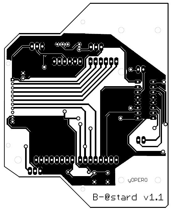
Line Following Robot - PCB board

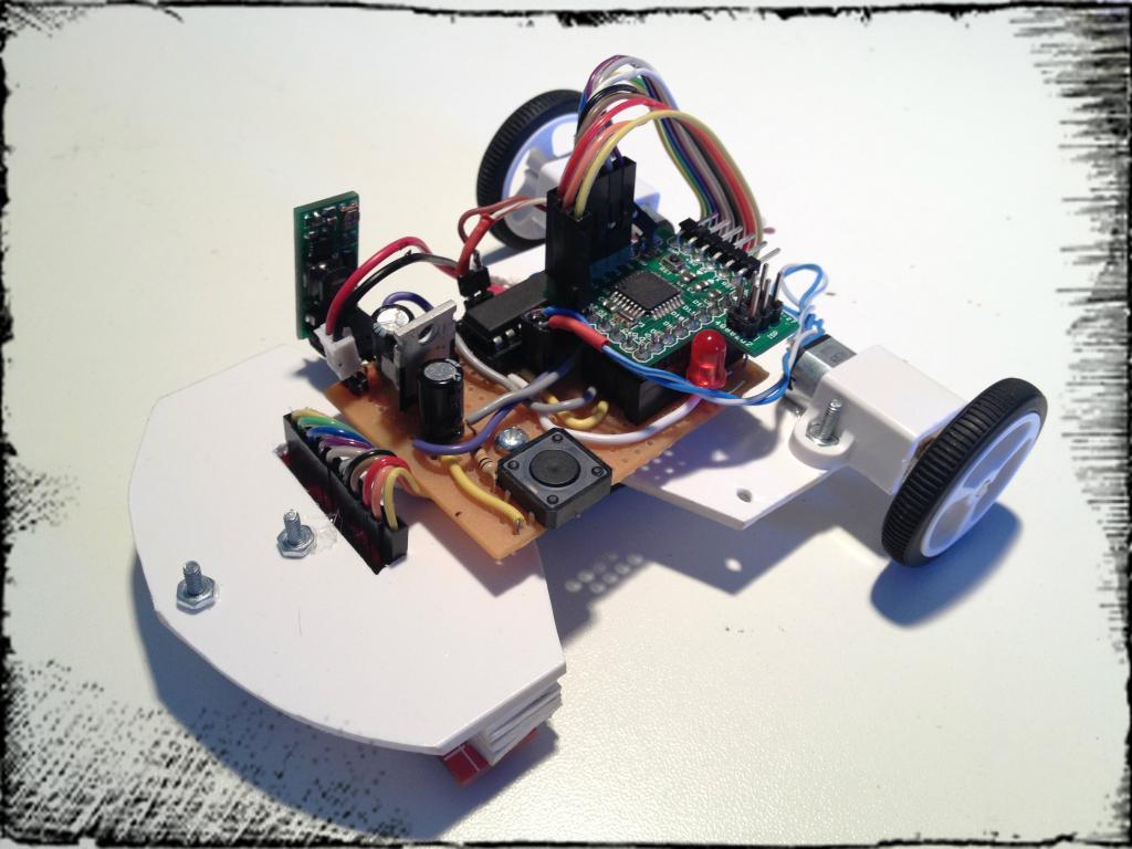
After experimenting with my first prototype I have decided to create a proper pcb, even though the actual setup gives a good performance I´d like to try out and see how the performance is with a more rigid material such as the pcb itself. here a few screenshots of the job done so far on the design front, I am planning to each the board as soon as I can.


Line Following Robot

Goal: Build hardware and software for a line follower robot(I think the category is called sniffer)

This robot has to go as fast as possible,  must be able to take sharp turns as low as 90 degrees and it has also to be able to read marks on the side of the main line.

I have started this project a couple of months ago and I have not done as much as I wanted due to work related task taking the most of my time.


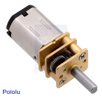
For the hardware I am going to use:

UPDATE: first prototype

In the software side I am going to do the programming using C on Atmel Studio v6.

The sensors are going to get analog values from which a "position" will be determinated. The aimed position is going to be the middle point.

In order to drive the motors in a efficient way I am going to use PD control (Proportional and Derivative).

Right now I am working in a telemetry system that allows me to find the best PD performance.

For this I am going to use a small Bluetooth module from DX JY-MCU Arduino Bluetooth Wireless Serial Port Module
and on the PC I hope to make an interface using python that will connect to the COM port and get the values send by the board and display them in a nice graph using smoothiecharts


UPDATE: Telemetry done:


Once the above goals are complete I'll jump to another more specific topics for the line follower such reading marks, taking sharp turns, etc.

So far I am still researching on the best way of programming the robot so I may get one of this this three styles:
  1. Reactive Style or reading sensors and actuating
  2. Behaviour control based on fancy state machines.
  3. Real time programming using a small OS or a basic scheduler.


Arduino Leonardo + Ethernet Shield

Escribo este post a raíz de una pregunta formulada en el foro de Arduino en español.
http://arduino.cc/forum/index.php/topic,106474.msg903626.html#msg903626

El problema: 

Los Ethernet Shields no fucionan con la Placa Vinciduino.

El razonamiento:

Los Ethernet shields usan los pines 10,11,12,13 en el Arduino Uno/duemilanove y el pinout es el siguiente:

Pin Arudino Uno pin microcontroller
10 SS
11 MOSI
12 MISO
13 SCK

En el diseño de Viciduino o Leonardo boards para aprovechar la mayor cantidad de pines del micro(Atmega32u4) se han movido los pines del SPI al conector ISCP

Y el pin SS ha sido asignado al Rx-LED


Pruebas realizadas:


He conectado los pines del ISCP de Vinciduino con los pines de arduino de la siguiente manera:
Eth Shield Vinciduino ISCP
11 MOSI
12 MISO
13 SCK
Ahora bien para poder coger la senal del SS(PB0) del micro he desoldado la resistencia del RXLED para poder soldar un cable y conectarlo al pin 10 del Ethernet shield:

Fucsia = resistencia a quitar
Rojo = pad donde soldé el cable que iría al pin 10 del ethernet shield.

Una vez realizadas las conexiones  me encuentro con que tampoco funciona, y me doy cuenta que el ansia ha podido conmigo ya que no he revisado el código de la librería Ethernet.
##(hacia mucho que no cogía el soldador)

Luego de revisar la librería Ethernet me encuentro con que el equipo Arduino ha editado el archivo w5100.h y han  creado un SS virtual en el pin 10(PB6) de Leonardo/Vinciduino.
Finalmente conecte el pin 10 de Vinciduino al pin1 10 del Ethernet shield y ha funcionado correctamente.

Solución Final:

Simplemente conectar los pines del SCK, MISO,MOSI del  ISCP en nuestra Vinciduino a los pines del ethernet Shield y también el pin  10 de Vinciduino al pin 10 de la Ethernet Shield.
Tal que así:

Vinciduino(Atmega32u4) + LUFA


  1. USB Virtual Serial
    1. Cambiar estas lineas en el makefile:
      1. MCU = atmega32u4
      2. F_CPU = 16000000
      3. BOARD = VINCIDUINO
    2. Por defecto viene el ejemplo echo.Usando hTerm envio datos y MCU devuelve lo mismo.
  2. USB Virtual Serial ADC
    1. Cambiar estas lineas en el makefile:
      1. MCU = atmega32u4
      2. F_CPU = 16000000
      3. BOARD = VINCIDUINO
    2. Por defecto viene la lectura analog0 y analog1(PF5 y PF4 en el 32u4)
    3. Edito/anhado la asignación de channels en "USBVirtualSerial-ADC.c".
    4. /*Cambio esto para que coincida con Vinci.
      ADC_CHANNEL0=PF0=ANALOG5
      ADC_CHANNEL1=PF1=ANALOG4
      ADC_CHANNEL4=PF4=ANALOG3
      ADC_CHANNEL5=PF5=ANALOG2
      ADC_CHANNEL6=PF6=ANALOG1
      ADC_CHANNEL7=PF7=ANALOG0
      /*
      if ((count = fread(&buffer, 1, CDC_TXRX_EPSIZE, &USBSerialStream)) > 0) {
      
         // if host sent a 0, send back value of ADC channel 0, if a 1 then channel 1
         // there is only one ADC with multiplexed inputs so only one channel can be converted at a time
         tempByte = buffer[0];
         if (tempByte == '5') {
          ADC_StartReading(ADC_CHANNEL0 | ADC_REFERENCE_AVCC); // start reading channel 0 in the background
          waitingForADCResult = 1;
      .
      .
    5. Finalmente para que coincida con la serigrafia de Vinciduino: 
      1. En hTerm envio 0 -->leo y recibo PF7 en el 32u4--->analog0 serigrafia Vinci.
      2. En hTerm envio 1 -->leo y recibo PF6 en el 32u4--->analog1 serigrafia Vinci.
      3. En hTerm envio 2 -->leo y recibo PF5 en el 32u4--->analog2 serigrafia Vinci.
      4. En hTerm envio 3 -->leo y recibo PF4 en el 32u4--->analog3 serigrafia Vinci.
      5. En hTerm envio 4 -->leo y recibo PF1 en el 32u4--->analog4 serigrafia Vinci.
      6. En hTerm envio 5 -->leo y recibo PF0 en el 32u4--->analog5 serigrafia Vinci.
  3. USB Virtual Serial I2C {pending}
  4. USB Virtual Serial LCD {pending}
  5. USB Virtual Serial SPI {pending}
  6. USBtoSerial {pending}
  7. USB Virtual_FreeRTOS {pending}

nRF24L01 + Arduino

I will keep working on the concept of IOT(internet of things).

Wireless connections are the standard of todays comunications therfore the IOT should follow this path.

Xbee are very reliable way of comunicating wirelessly however this devices are very expensive, I set myself to find a cheap and reliable way of comunicating devices using RF, so after sometime I expend reading on Internet I finally found the nRF24L01 module from Iteadstudio for $ 5.50 nRF24L01 module

They provide a couple of code examples but they pretty poor.
Luckily I found one library in the Arduino website called MIRF and another most powerfull library created named nRFL2401 http://maniacbug.wordpress.com the later the one I am going to use in this write up.

-----Descarga la libreria nRFL2401 ----

First of all we are going to setup the hardware connections;

----------------------------------------

nRFL01 Arduino nRFL01 Arduino
IRQ 8 MISO 12
MOSI 11 SCK 13
CSN 10 CE 9
Vcc 3.3V Gnd Gnd
----------------------------------------

As per the datasheet specs it is very important to provided 3.3 Volts to the module(Do not provide 5V as it will damage your module)

Once we have the connections set we are going to start by loading the "Getting started" example  from the nRFL01 library.

Once you have loaded the example open up the Serial Monitor on the Arduino IDE a 57600 , if all went OK you should see something like this:


ROLE: Pong back
STATUS = 0x0e RX_DR=0 TX_DS=0 MAX_RT=0 RX_P_NO=7 TX_FULL=0
RX_ADDR_P0-1 = 0xf0f0f0f0d2 0xf0f0f0f0e1
RX_ADDR_P2-5 = 0xc3 0xc4 0xc5 0xc6
TX_ADDR = 0xf0f0f0f0d2
RX_PW_P0-6 = 0x08 0x08 0x00 0x00 0x00 0x00
EN_AA = 0x3f
EN_RXADDR = 0x03
RF_CH = 0x4c
RF_SETUP = 0x07
CONFIG = 0x0f
DYNPD/FEATURE = 0x00 0x00
Data Rate = 1MBPS
Model = nRF24L01
CRC Length = 16 bits
PA Power = PA_HIGH


Si los resultados de las variables son un montón de Ceros "0" revisa tus conexiones porque algo no debe estar conectado correctamente.
Este primer modulo sera el receptor.
Si todo va bien carga el mismo sketch"Getting started" a otro arduino.
y sigue el mismo procedimiento este segundo  modulo sera el transmisor, para ponerlo en modo transmision abre el Serial  Monitor de Arduino y escribe una 'T' y veras que los transmisores empiezan a comunicarse:

Now sending 9369...ok...Got response 9369, round-trip delay: 27
Now sending 10399...ok...Got response 10399, round-trip delay: 29
Now sending 11431...ok...Got response 11431, round-trip delay: 27
Now sending 12462...ok...Got response 12462, round-trip delay: 28

Arduino + WebSockets II

Please read the first part of this serie: http://yopero-tech.blogspot.com/2012/02/arduino-websockets.html

This project describes how to use WebSockets to display data  taken from Arduino and broadcast it to any Browser with WebSocket support. Test your browser here: http://websocket.org/echo.html

First of all we need to decide what data to display and  what to control in Arduino from the  web page .

In this example I am going to control 3 remote controlled relays that you can buy at your hardware store and I want to display the values from 2 temperature sensors.(DS18S20)

This project is composed out of 3 main parts of software apart from the hardware(Arduino Board):


  1. WebSocket  Server:
    1. Python
    2. Autobahn
      1. Twisted
        1. PySerial
  2. MCU (Micro Controller Unit)
    1. Arduino Board(Vinciduino in my case).
    2. Arduino IDE or AVR studio.
  3. Client:
    1. Any web server, I use xampp or python to test as localhost.
             

The WebSocket server I setup is run under Windows XP:

First thing is to install Python in my case I have used v 2.7

On Python I have installed the following packages:

If you have installed all of the above, download the files of the project from here:
Serial2WS.rar
Now that we have the WS server I will jump to the Arduino side of the project, as said above I will control 3 lights interactivity and I will get real time data from 2 temperature sensors.
To accomplish that I have hacked the remote control and connected it to the Arduino
You can see my setup in the video at the end of the post.


The Arduino sketch for my setup at the end of this entry( too long to put  in the middle of the entry)

This sketch sends the values of the 2 temperature sensors with id = 1 or 2 in format JSON
Id  \t value
I would say that this is the most important part of the project, send JSON formated data from arduino to python and then python to digest it and broadcast via WS. 
   celsius = (float)raw / 16.0;
   
   //Sending JSON 
    Serial.print(id);
    Serial.print("\t");
    printFloat(celsius , 0);    
    Serial.println();
    //finish sending JSON
later this data is read by the WebSocket server and dispatch to the browser.
def lineReceived(self, line):
      try:
         ## parse data received from MCU
         ##
         data = [int(x) for x in line.split()]

         ## construct PubSub event from raw data
         ##
         evt = {'id': data[0], 'value': data[1]}

         ## publish event to all clients subscribed to topic
         ##
         self.wsMcuFactory._dispatchEvent("http://example.com/mcu#analog-value", evt)

         log.msg("Analog value: %s" % str(evt));
      except ValueError:
         log.err('Unable to parse value %s' % line)


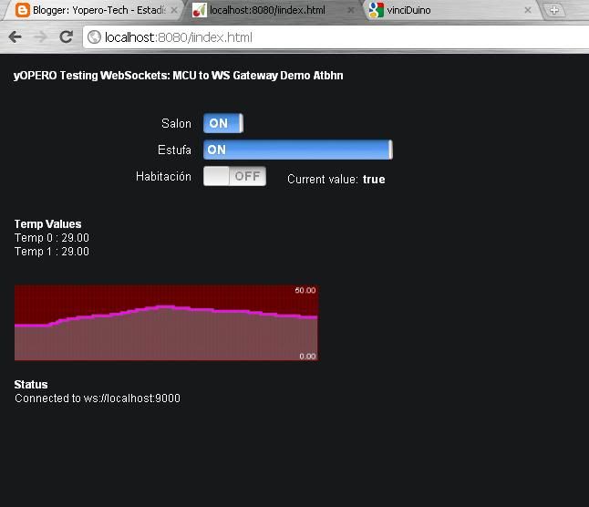
In order to display the values given by Arduino and received by the Websocket server I am  using Smoothie Charts; is a really small charting library designed for live streaming data.( http://smoothiecharts.org/)


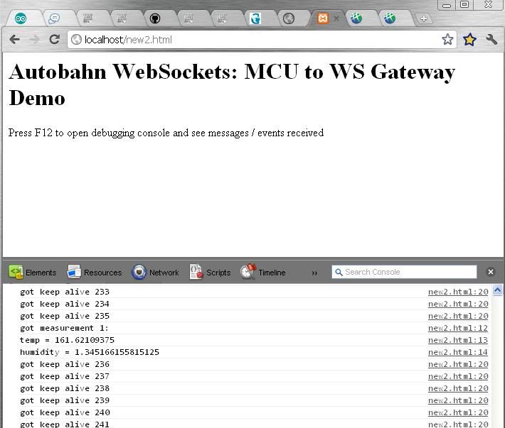
The final results as you see in the video and screenshots.


In the future I will try to load the WebSocket(C++)client directly to a Arduino with an ethernet shield to avoid the use of a PC, but I am not sure how it will impact the infrastructure side of my LAN(opening ports).


Click "Mas informacíon" to preview the Arduino code

Arduino + WebSockets I


“”WebSockets””


Lately I have been exploring ways of plotting data from a MCU to a web browser, at first I was using arduino and firmata which basically allows you to get nice graphics but implementing it to be connected to a webserver was kind of difficult.
Then we have the option of using Ethernet shields but it lacks of enough memory to write good looking web pages, this can be fixed by using short php commands and the process the rest on a webserver however this solutions only applies to projects that do not need speed and real time connections between server and client/web browser.
An example of that is controlling lights, in this case we only need that the light switches on we do not really care about speed, but imagine if you want to control via web an AUV(Autonomous Underwater vehicle) the scenario changes dramatically because what is needed is accuracy and real time communication between web browser and server which is connected to our MCU via RS232,XBEE,Wireless,Ethernet, etc.(I know this scenario is not very common but hey… this paper and websockets technology is experimental so the scenarios too).
I have also explored Python and Pyserial and  I must say that python is so powerful as you can get lots of things with few lines (although you need first to learn it J)
After exploring Python and some packages such as wxPython, PyQt4, PyGtk you can build nice apps to be run on your computer but it was not good enough for me I really like the look of a webpage so I kept searching until I read something about a real fast technology tested on financial applications, that’s the way I heard about WebSockets and then I thought I may use it with my Arduino.
After looking on internet I found that some people has already used web sockets to communicate with a MCU; people from http://mbed.org/cookbook/IOT uses Tornado a python server but unfortunately it does not run on windows due to a Unix dependency.
As I had my computer already setup with python I went looking for a stand alone websocket package, it took me awhile to find a nice piece of code in http://www.tavendo.de/autobahn/ Autobahn provides client and server implementations of WebSockets for Python and Android.
They have the repocitory in github: https://github.com/oberstet/Autobahn and a google group @ http://groups.google.com/group/autobahnws
After contacting with Tobias O. the owner of this repository I presented him what I want to achieve and he helped me a lot.

Now some theory about WebSockets:

What are WebSockets?

“”WebSockets is a technique for two-way communication over one (TCP) socket, a type of PUSH technology. At the moment, it’s still being standardized by the W3C; however, the latest versions of Chrome and Safari have support for WebSockets.””


What do WebSockets Replace?

Although the real purpose of WebSockets. was not primarily designed to replace any of the things that are already in place and working well. For example, it was not designed to be a low-overhead version of AJAX. The purpose is to provide a bidirectional, low latency, full duplex, communication channel between the browser and server. It's real purpose is to enable a new domain of web applications or to improve current ones that are abusing HTTP to achieve bidirectional communication.
But…..Websockets can replace long-polling. This is an interesting concept; the client sends a request to the server – now, rather than the server responding with data it may not have, it essentially keeps the connection open until the fresh, up-to-date data is ready to be sent – the client next receives this, and sends another request. This has its benefits: decreased latency being one of them, as a connection which has already been opened does not require a new connection to be established. However, long-polling isn’t really a piece of fancy technology: it’s also possible for a request to time-out, and thus a new connection will be needed anyway.
Many Ajax applications make use of the above – this can often be attributed to poor resource utilization.
Wouldn’t it be great if the server could wake up one morning and send its data to clients who are willing to listen without some sort of pre established connection? Welcome to the world of PUSH technology!


Next post I will describe the technical part of this project.

Tennis/Padel Scoreboard II

Aprovechando esta primera semana del año he terminado este proyecto que tenia pendiente.

 He aquí un vídeo de su funcionamiento:


 ..y este link a la primera parte del post Tennis/Padel Scoreboard

Vinciduino-Cargar bootloader con Arduino UNO.

Para realizar la  carga del bootloader en una placa Vinciduino con un Arduino UNO/Diecimila necesitaremos lo siguiente:

1.       Hardware.

a.       Arduino UNO +cable usb

b.      Vinciduino  +cable usb

c.       Cable para conectar Arduino UNO con el ISP de Vinciduino. (6 cables macho por un lado hembra por otro)


d.      Ordenador.

2.       Software.

a.       Arduino IDE 21 o 22(testeado con ambos)


c.       Arduino v 1.00 RC2.

d.      SO Windows 7.


Primero necesitaremos tener instalada la versión Arduino IDE 21 y Arduino IDE 1.00 RC2.

Ahora necesitamos añadir este archivo ArduinoISPleonardo en el folder “examples” de Arduino IDE 21.


Ahora conectamos nuestro Arduino UNO  abrimos Arduino IDE 21 seleccionamos en Tools.

Bord= Arduino UNO

Serial Port= COM del Arduino

Abrimos y  cargamos  el sketch que hemos añadido en “examples”


Para estar completamente seguros de que nuestro hardware es decir la placa Vinciduino esta con funcionando correctamente debemos hacer la siguiente comprobación:


Enchufar la placa Vinciduino mediante un cable USB al ordenador, si todo esta correcto veremos el siguiente mensaje:


<<Para las personas que hayan soldado las placas:
Es muy importante realizar la comprobación descrita arriba antes de iniciar la carga del bootloader ya que hay la posibilidad de pensar que el proceso de cargar el bootloader no funciona cuando en realidad lo que no funciona es nuestro hardware debido a soldaduras mal hechas o componentes mal ubicados>>

El siguiente paso es conectar nuestro Arduino UNO a Vinciduino.

Mediante el  conector ISP solo y únicamente ya que he intentado hacerlo como se hace con Arduinos (http://arduino.cc/es/Tutorial/ArduinoISP)y no funciona. 


Una vez que tenemos la conexión como en la imagen de arriba procedemos a cerrar ArduinoIDE 21 y abrir Arduino 1.00 RC2. En “Tools” seleccionamos:

Board= Arduino Leonardo

Serial Port = COM del Arduino

Programmer = Arduino as ISP


Una vez tengamos todos los settings procedemos a cargar el bootloder:


Presionamos el botón de reset de la  Vinciduino(para ponerlo en modo bootloader) he inmediatamente hacemos click en “Burn Bootloader”.


Entonces los leds rx,tx y “L” de Arduino UNO parpadearan intermitente durante aproximadamente 1 minuto. Si todo va bien recibiremos la confirmación:


El Paso siguiente es conectar el Vinciduino a nuestro ordenador mediante usb, he probado en dos ordenadores con Windows 7 y en ningún caso reconoce el driver automáticamente por lo que deberemos instalarlo. Debemos ir a al administrador de dispositivos de Windows :


Hacemos click derecho en  Leonardo y actulizamos el controlador seleccionando la siguiente ruta que esta en  la ruta donde hemos instalado Arduino 1.00 RC2.

En mi caso:

C:\Users\yopero\Desktop\arduino-1.0-rc2\drivers


Finalmente volvemos a verificar en el administrador de dispositivos:


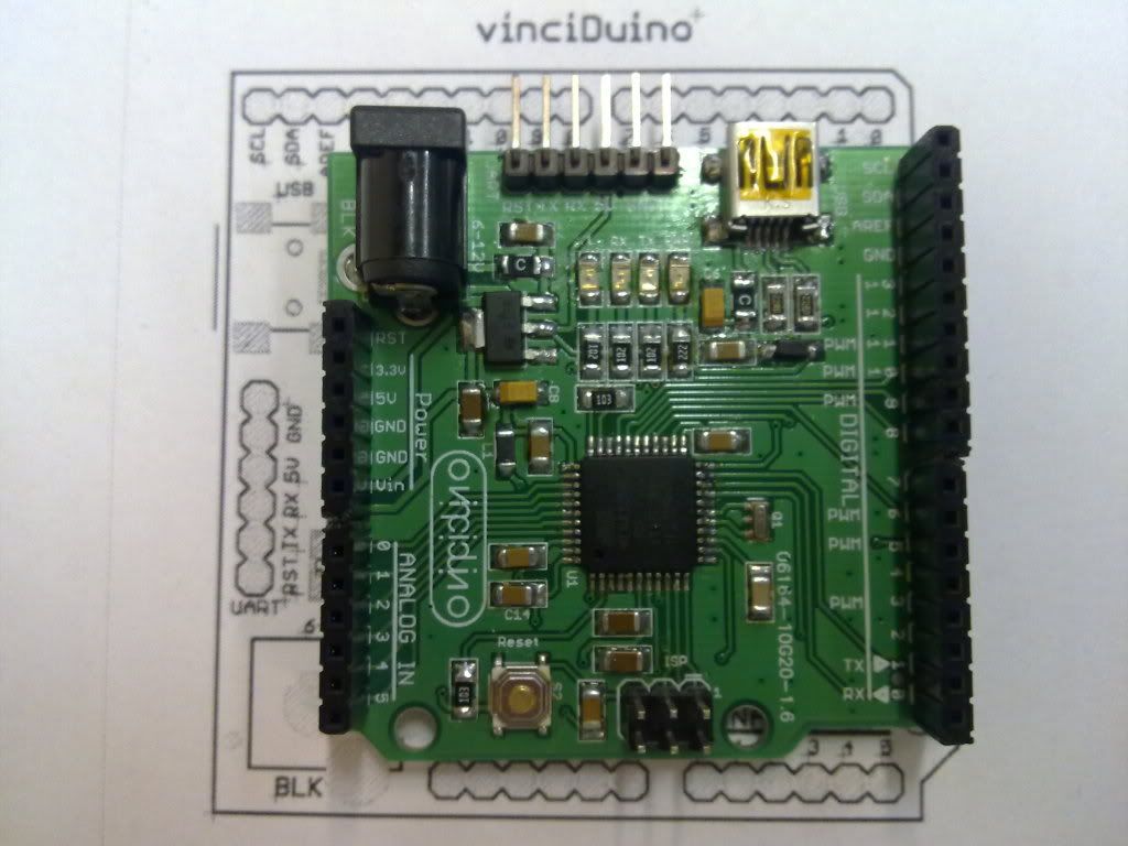
Vinciduino


He empezado a colaborar con el Vinciduino team.(https://bitbucket.org/fmalpartida/vinciduino/wiki/Bienvenido)


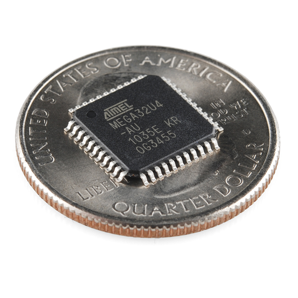
El objetivo es la creación de un nuevo clon de arduino Leonardo usando un ATmega32U4 y componentes SMD.


El objetivo de este grupo es tratar de llevar el open hardware un paso mas allá del estado existente. 
  • Cualquiera puede ir a la página de la placa y descargarse el esquemático, layout o los ficheros de fabricación para mandar a un fabricante de PCBs, en nuestro caso hemos usado ITEAD para la primera versión de la placa, donde por menos de 30 euros te dan 10 placas con un acabado profesional.
  • Una vez encargadas las placas se va a un distribuidor de componentes electrónicos y se carga el carrito de la compra, donde en un click de ratón conseguimos todos los componentes necesarios. Cualquiera que no tenga unos conocimientos medios en electrónica no sabrá seleccionar los componentes para montar la placa, por lo que si queremos que la difusión de la placa sea máxima hay que facilitar un carrito, a la vez que sirve para ver el coste de la placa.
  • Recibidos las placas y componentes cualquiera se la puede montar siguiendo elesquema de montaje, descargar el entorno Arduino o de Atmel para programar la placa teniendo un foro donde preguntar dudas y compartir ideas/proyectos. 


Aqui un par de fotos de mi Vinciduino montado, aunque todavia no he probado el bootloader o arduino IDE. Debo confesar que es muy gratificante tener una de estas placas montadas, hasta ahora me habia dedicado a crear mis PCB y el acabado no tiene nada que ver, con un placa realizada por maquinas hasta soldar SMD se hace muy facil.


DomoLeroyDuino

Sistema de control de encendido y apagado de dispositivos eléctricos a través de control remoto. Se trata de un sistema que se compone de uno o varios receptores (enchufes, interruptores y portalámparas) y un mando a distancia. Los enchufes de esta gama permiten dos funciones: la de encendido y apagado de los dispositivos eléctricos conectados al enchufe. El mando a distancia de esta serie permite el encendido y apagado de 8 líneas de enchufes, esto lo he comprado en Leroy Merlin y vienen en packs de 3 enchufes y un mando.

Para poder controlar esos enchufes necesitamos integrar arduino al control remoto existente.
Dicho control remoto consta de 2 botones de encendido( 1 y 2) y dos botones de apagado (1 y 2) además de un mini interruptor de  4 posiciones  A,B,C y D.
 Es decir que por cada canal seleccionado podemos controlar dos enchufes haciendo un total de 8.
Para controlar los 8 enchufes necesitamos por tanto 8 pines de Arduino:
  1. Seleccionar canal A
  2. Seleccionar canal B
  3. Seleccionar canal C
  4. Seleccionar canal D
  5. Encender 1
  6. Apagar 1
  7. Encender 2
  8. Apagar 2
 Por ejemplo:
Para encender el 1 en el canal A, ordenaremos Arduino  encender el pin del Canal A + el pin de Encender 1.
Para apagar el 2 en el canal B, ordenaremos Arduino encender el pin del Canal D + el pin de Apagar 2

Aun no tengo decidido como controlar los encendidos y las posibilidades son las siguientes:
  • Ethernet Shield.
  • RTC Real time clock, con el que dejare todo programado en el atmega.
  • A través de un PC enviando comandos via Serial port.
Luego de las consideraciones teóricas es hora de encender nuestro multímetro y ponernos a investigar como funciona el control remoto.
Los botones de encendido son simples de controlar usando un relé o un transistor(x4).
 El mini interruptor de 4 posiciones requiere un poco mas de trabajo ya que la forma en que se conecta (ver foto detalle en la parte inferior derecha:


Cuando esta en posición A conecta GND con la linea de A (dos patillas) esto lo podríamos solventar con un relé pero las lineas(ABCD) deben estar aisladas ya que si hay contacto entre ellas solo el canal A estaría disponible.Mi solución es tener una linea de control para cada patilla haciendo un total de 8 controles aislados aunque luego en el arduino solo necesitaremos 4 ordenes ya que activaremos dos con un solo pin pero estas deben estar aisladas.
Había pensado en usar relés pero al pensar que necesito 12 me parece que ocupara mucho sitio, otra posible solución es usar un multiplexer 74hc585 o 12 transistores NPN.
Yo lo haré con 12 transistores y el circuito es el siguiente. Muy importante conectar el GND del mando remoto y de Arduino.


Update:

La aplicación para el control domotico ya esta terminada y testeada, simplemente queda determinar que items controlar .
La aplicación esta hecha en python :